Introduction
When I need to change the functions of a fixture I use the DMX bus to drive them. This article presents you the software code I use (in C language) to decode the data. I’m using it on PIC MCU from Microchip. It may be possible to adapt the code for other hardware.
DMX protocol presentation
Before going deeper in the code, I recommend you to have look on Wikipedia website. Nevertheless here after the frame:
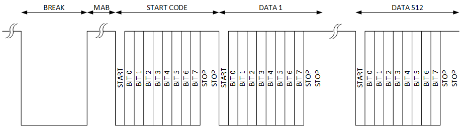
When the bus is idle, the line is in a high level. The beginning is marked with a break. The break is 88µs long at minimum and 100ms maximum. After the break with have the Mark After Break of 8µs at least.
The first data send is the « Start Code ». The start code is used to select a part or a specific function of the fixture. in the general equipment, the start code is waited at 0x00. This code is for dimmer in the standards. Other codes are available in the ESTA liste. After the start code we have 512 bytes, one for each channel. Each byte is marked with a start and 2 stops.
It’s an easy protocol.
How to get data?
To get the data we will use the PIC’s UART. To decode the frame, we will use a state machine.

- IDLE : It’s the default state.
- When the UART get a FRAME ERROR it means that the ligne state to long at 0. It’s the BREAK. During this period we have to read the 0x00 in the UART until we get a new FRAME ERROR. This happens when we are in the MAB.
- The state machine is then in START. As long as we detect the FRAME ERROR we are in the MAB of the DMX bus. But as soon as the data is 0x00 we get the START CODE. We can go to the DATA state.
- In DATA, we simply get the 512 channels. In the program, we only store in memory the data we have to use. When the internal counter is at 513, the FLAG is set to say that we have a new data available.
The code
UART configuration
First, the UART has to be configured in receive mode at 250kpbs. To be more flexible with the Software, I do a re-naming of the registers with a #define.
|
1 2 3 4 5 6 7 8 9 10 11 12 13 14 15 16 17 18 19 20 21 22 23 24 25 26 27 28 29 30 31 32 33 34 35 36 37 38 39 40 |
#define DMX_ADR_RCSTA RC1STA #define DMX_REG_RCSTA 0b10000100 /* |||||||!- RX9D disabled ||||||!-- OERR Overrun Error bit disabled |||||!--- FERR Framing error enable ||||!---- ADDEN Adress detect disable |||!----- CREN Disabled <== Has to be switch on to operate ||!------ SREN Don't care in slave mode |!------- RX9 8bits !-------- SPEN enabled */ // #define DMX_RX_ENABLE RC1STAbits.CREN //used for RX switch ON/OFF #define DMX_ADR_BAUDCN BAUD1CON #define DMX_REG_BAUDCN 0b00000000 /* |||||||!- ABDEN disabled ||||||!-- WUE disabled |||||!--- Not used ||||!---- BRG16 8bit baud generator |||!----- SCKP non inverted ||!------ Not used |!------- RCIDL cleared !-------- ABDOVF disabled */ //Baud Rate = 250kbps (@FOSC=16MHz) #define DMX_ADR_SPBRGL SP1BRGL #define DMX_REG_SPBRGL 0 #define DMX_ADR_SPBRGH SP1BRGH #define DMX_REG_SPBRGH 0 #define DMX_ADR_RCREG RC1REG #define DMX_INT_RXIF RC1IF #define DMX_INT_FERR RC1STAbits.FERR #define DMX_INT_OERR RC1STAbits.OERR #define DMX_BIT_RXEN RC1IE |
Than in the DMX library we have the initialization function.
|
1 2 3 4 5 6 7 8 9 10 11 12 13 14 15 16 17 18 19 20 21 22 23 24 25 26 27 28 |
void DMX_UART_Init(void) { /* Function : DMX_UART_Init * Argument : None * Returns : None * * Description : * Configure the UART and TIMER for the DMX reception * The UART RX has to be switched on before using it. */ //configuration UART DMX_ADR_TXSTA = DMX_REG_TXSTA; DMX_ADR_RCSTA = DMX_REG_RCSTA; DMX_ADR_BAUDCN = DMX_REG_BAUDCN; DMX_ADR_SPBRGL = DMX_REG_SPBRGL; DMX_ADR_SPBRGH = DMX_REG_SPBRGH; DMX_ADR_RCREG = 0; //TIMER configuration for timeout detection DMX_BIT_WDGIE = 0; DMX_REG_WDG = 0; DMX_INT_WDG = 0; //Initialisation of DMX status DMXState = DMX_BUS_IDLE; DMXRx.NEW_DATA = 0; } |
Some functions to start and stop the UART.
|
1 2 3 4 5 6 7 8 9 10 11 12 13 14 15 |
void DMX_UART_Start() { char dummy = DMX_ADR_RCREG; DMX_RX_Switch(1); DMX_RX_INT_Switch(1); DMX_Timeout_Switch(1); } void DMX_UART_Stop() { DMX_Timeout_Switch(0); DMX_RX_Switch(0); DMX_RX_INT_Switch(0); char dummy = DMX_ADR_RCREG; } |
The interruptions
To get the state machine operating, we need events. To get them, we use the IT coming from UART.
|
1 2 3 4 |
if(DMX_INT_RXIF){ DMX_UART_IT(); } //DMX_INT_RXIF is UART IT Flag (RC1IF for ex) |
Decode function
Don’t forget to add in the h. file of the library the enumerator declaration
|
1 2 3 4 5 6 |
typedef enum { DMX_BUS_IDLE, DMX_BUS_BREAK, DMX_BUS_START, DMX_BUS_DATA, }DMX_BUS_STATE; |
And naw we have the function
|
1 2 3 4 5 6 7 8 9 10 11 12 13 14 15 16 17 18 19 20 21 22 23 24 25 26 27 28 29 30 31 32 33 34 35 36 37 38 39 40 41 42 43 44 45 46 47 48 49 50 51 52 53 54 55 56 57 58 59 60 61 62 63 64 65 66 67 68 69 70 71 72 73 74 75 76 77 78 79 80 81 82 83 84 85 86 87 88 89 90 91 92 93 94 95 96 97 98 99 100 101 102 103 |
/*----------------------------------------------------------------------------*/ /* VARIABLES GLOBALES */ /*----------------------------------------------------------------------------*/ DMX_BUS_STATE DMXState; unsigned int count; /***********************************************************************/ /* STATE MACHINE */ /***********************************************************************/ void DMX_UART_IT() { /* Function : DMX_UART_IT * Argument : None * Returns : None * * Description : * State machine for the DMX protocol */ //Variable declaration char dummy; //is used to get UART Rx register char i; //d ut de la fonction switch(DMXState) { case DMX_BUS_IDLE: //DMX is in IDLE state. The RX starts to get low. If a framing //error IT occurs, that means that the bus is in START if(DMX_INT_FERR) { //Framing error was detected ==> BREAK condition DMXState = DMX_BUS_BREAK; DMX_REG_WDG = 0; } dummy = DMX_ADR_RCREG; DMX_REG_WDG = 0; break; case DMX_BUS_BREAK: //DMX is in BREAK. The UART will receive continously null data //the data will be discared until a new framing error is detected if(DMX_INT_FERR) { //Framing error was detected and means MAB on the DMX bus DMXState = DMX_BUS_START; DMX_REG_WDG = 0; } dummy = DMX_ADR_RCREG; break; case DMX_BUS_START: //DMX is in MAB and continue to send FERR sequence //when RCREG will get a 0 value without FERR it will be the START //mark. if(DMX_INT_FERR) { //still in MAB dummy = DMX_ADR_RCREG; DMX_REG_WDG = 0; } else { //get value dummy = DMX_ADR_RCREG; if(dummy == 0) { //it's the START code got to DATA DMXState = DMX_BUS_DATA; count = 1; DMX_REG_WDG = 0; } else { //wrong start code. Go to IDLE, waiting new sequence DMXState = DMX_BUS_IDLE; } } break; case DMX_BUS_DATA: //The bus is sending data. waiting for the selected address dummy = DMX_ADR_RCREG; DMX_REG_WDG = 0; //check if in the address, the DMX bus load the new value. if((count >= DMXRx.DMX_ADDRESS) && (count <= (DMXRx.DMX_ADDRESS + CHANNEL_SIZE))){ i = count - DMXRx.DMX_ADDRESS; //loading value: DMXRx.DMX_DATA[i] = dummy; } count++; //When the last data is received, the New DATA flag is set and //the state machine returns to IDLE if(count == 513) { DMXRx.NEW_DATA = 1; DMXState = DMX_BUS_IDLE; } break; } } |
Data structure
As you have seen in the code, I use the DMXRx variable. It’s a structure who contains, the device address, a table sized for the number of channels and a flag new data.
|
1 2 3 4 5 6 7 8 9 10 11 |
//DMX Message structure typedef struct{ unsigned int DMX_ADDRESS; unsigned char DMX_DATA[CHANNEL_SIZE]; unsigned NEW_DATA : 1; }DMX_STRUCT; /*----------------------------------------------------------------------------*/ /* GLOBALES VARIABLES */ /*----------------------------------------------------------------------------*/ DMX_STRUCT DMXRx; |
The timeout
You can make the code work without timeout. On my point of view it’s better to have. It’s a simple counter and when it’s higher than 100ms it push an IT who will reset the state machine and the UART.
|
1 2 3 4 5 6 7 8 9 10 11 12 13 14 15 16 17 18 19 |
void DMX_timeout_IT() { /* Function : DMX_timeout_IT * Argument : None * Returns : None * * Description : * When the timer overflows, the interruption reset the state machine in * IDLE mode. * IT is also cleared. */ //when the timer overflows, the timeout on the DMX is set. DMXState = DMX_BUS_IDLE; DMX_INT_WDG = 0; RC1STAbits.OERR = 0; RC1STAbits.FERR = 0; RC1REG = 0; } |
What’s next?
In your main() function, who can have a loop and when a new data received, you can generate a PWM, analog output etc. I use the flag DMWRx.NEW_DATA to detect the new data and to update the output.
That’s all.