Introduction
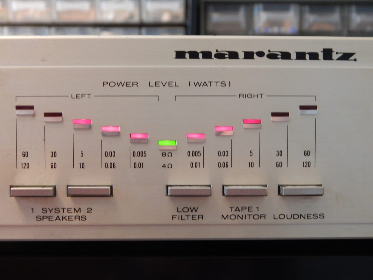
A guy bring to me a MARANTZ PM350 amplifier. He says that to have a little sound the volume button has to be set to the maximum. And, it only works on left channel. The PM350 is a vintage (1980) audio amplifier designed by MARANTZ. I used it several years and the sound is very good and the response is flat from 10Hz to 28kHz.
First diag
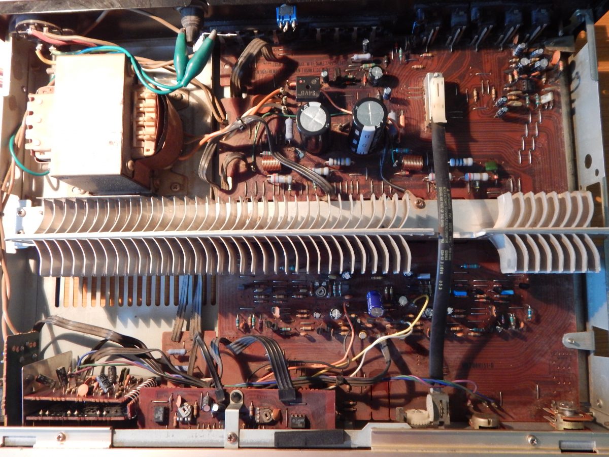
So, let’s go and open the amplifier… OMG!
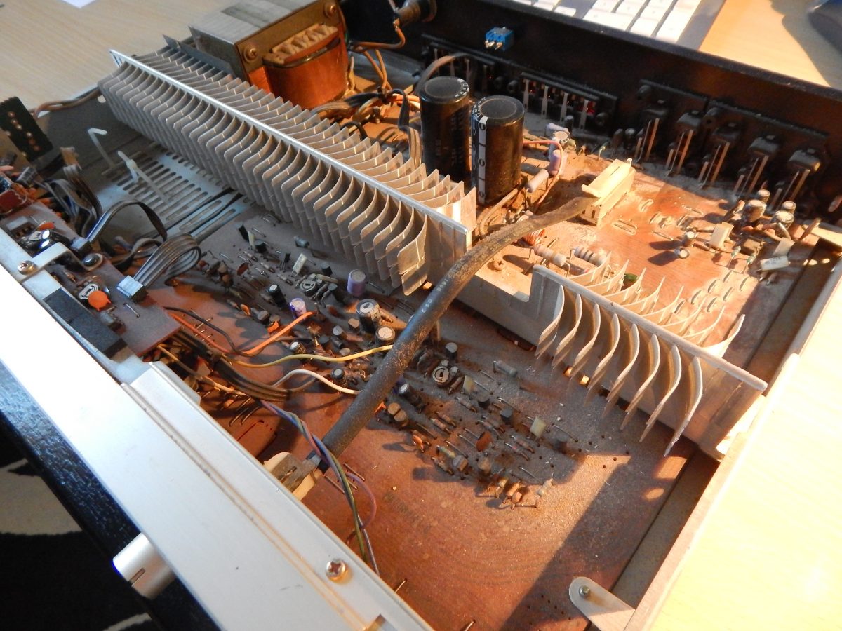
Before investigation a full cleaning is requested. I used solder flux cleaner. It’s not the best but it removed mostly the dust.
The work to do on this amplifier will be :
- Replace main chemical cap
- Check transistors on right channel
- Check operating point on left channel
Reparation
Re-Cap
One of the first thing to do is to replace all chemical capacitors. With the time the value decrease and especially when they’re near heating elements (like the big resistors).
There are no difficulties to find new caps. The package doesn’t impact a lot as you have space. Just a point about the main energy storage. The amplifier is designed for 220V. But since 1996 in France, the power supply is under 230V. As the caps are directly connected to the diode bridge, voltage increases also about 3V under 230V. So initial 45V caps are replaced with 50V (Part : UVY1H682MRD 6800µF 22x50mm).
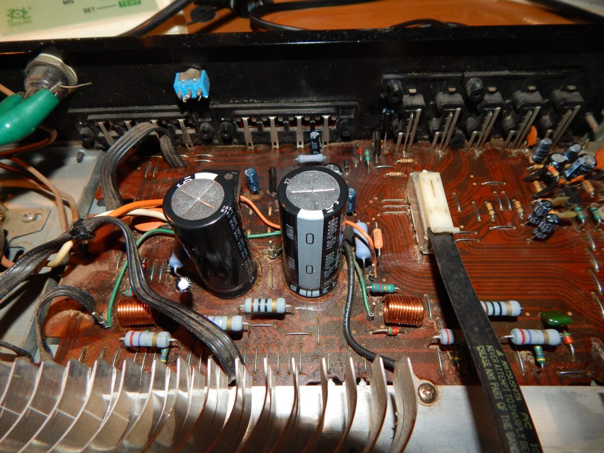
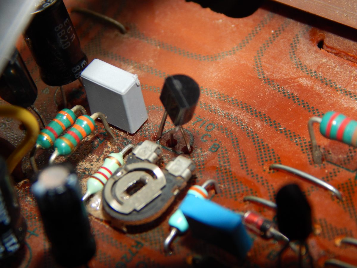
Note: there is a small cap ahead the wires and under the big cap. It’s rooted close to a power resistor. By pushing it away, the cap is less heated.
Left Channel check
All transistors are fine and I just corrected the output quiescent current. But still no sound! The problem comes from QN05 and QN04. The schema is:
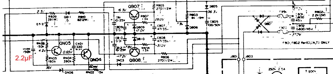
When you start the amplifier, QN04 charge CN01 capacitor and until QN04 get blocked, it drives QN02 and QN01 (see on next schema) to mute the output stage. When the power supply decrease, QN05 reset capacitor. I don’t know why, but there was a ripple on the 36V and it reset constantly the capacitor! I just increase the power capacitor CN02 to 2.2µF and it works. Maybe a broken chemical cap in stock.
Right Channel
Yep, almost transistors are dead! The amplifier schema is:
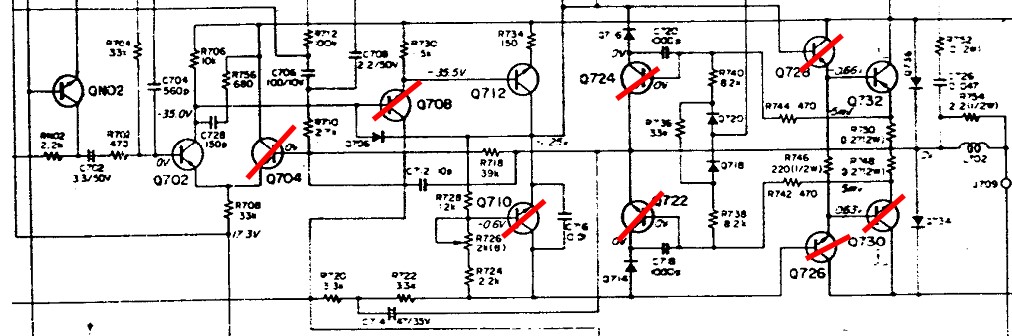
To fix this all, I used the following equivalences:
- Q702 and Q704 2SA750-E => 2SA872E (or KSA992FBU)
- Q708 2SC1400E => 2SC1775A
- Q710 2SC945P => 2N2222A
- Q722 2SC945Q => KSC945CYBU (2N2222A should also work)
- Q724 2SA733Q => 2N2907A
- Q726 2SD667C/D => KSC2383OTA
- Q728 2SB647C/D => KSA1013OTA
- Q730/Q732 2SC2578/2SA1103 => 2SC5200/2SA1943
Note: The PM350 is designed for transistor with central collector pin. Some equivalences have the base in the middle. So you have to twist pins… as you can.
Q702 and Q704 are mounted in comparator. You can use plenty of transistor for this stage. Q710, I recommended you to choice a transistor with a higher Ic current. I also reduce the quiescent voltage from -1.25V as noticed in the schematic to -1.00V. To do this, R724 is replaced with a 1.2kOhms and R728 increase to 3kOhms.
WARNING before powering up set the potentiometer to the max. (Otherwise, you will blow the fuse… as I do…). Then trim the potentiometer in order to have a quiescent current on the output stage about 10mA.
Some information about Q712. Original transistor is a 2SD666B/C. I tried to replace it by a MPS8099. It works but the TO92 package will get hot and I won’t to reduce the quiescent current for this stage. Probably a TO1 or TO5 is more suitable. Whatever, original transistor work fine so I let it in place.
As far as I understood, Q724 and Q722 limits the Base current of the output stage when the output voltage rise. I think this very useful to avoid “pop’s” sound when turning off the amplifier as it cuts output stage.
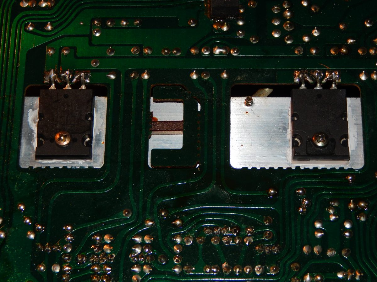
The power transistor are mounted bottom. Original package is TO-3PN but you can set a TO-264 inside. Don’t forget isolator and thermal pad!
Tests
I checked with the oscilloscope the output over the frequency range. And everything is OK. Test with music confirms that even with this changes, right and left sounds same. Before closing the box, I also cleaned the volume potentiometer to prevent from scratchs.
Extra-Infos:
Electronic device killed:
- The 1.5A fuse… and of course no one left
- 2x BC547B… Overvoltage
- KSC945… Don’t know why
External links:
AudioVintage for transistors equivalences informations
Overview
The green cable was used to shunt the fuse holder to a SMD fuse.
See you,